
 sales@analogmodules.com
 1-407-339-4355


OSCILLATION IN AMPLIFIERS
Most amplifiers work without problems, but in some cases oscillations may occur with high frequencies/high gains and/or poor layout. The first step is to measure the frequency and amplitude of the oscillation. Use the internal triggering of an oscilloscope to stabilize the waveform. Oscillations around the 3dB bandwidth of the amplifier are usually due to input/output feedback. Higher frequency oscillations may only be visible on a spectrum analyzer. They may cause waveform distortion and be affected by touching the amplifier on power and signal cables. This type of oscillation is usually in the hundreds of Megahertz or Gigahertz range, and is frequently caused by the input or output device parasitically oscillating. To solve oscillation problems, the source of the oscillation must be located. This may be the amplifier itself or components and leads outside the amplifier.
CHECK THE BASIC AMPLIFIER
To determine if the amplifier is faulty, make sure that the output cable is correctly terminated and remove all inputs including cables and lengths of wire. If the oscillation persists, verify that the output load does not have excessive capacitance (more than a few pf). This could cause a mismatch at high frequencies resulting in standing waves on the output cable. If this is suspected, try different cables, different cable lengths, and reduce the load capacitance. One fix is to insert a resistor of a few ohms in series with the amplifier output. (Try 1/8 watt 10Ω carbon composition). This resistor damps out reflections due to line mismatches but results in a gain and output swing reduction. For long lines, it may be necessary to back-terminate the line with a series resistor equal to the characteristic impedance of the line, resulting in a gain and swing loss of 6dB. Long output cables may attenuate high frequency signals. Special line drivers are available to compensate for this. If output cable problems are suspected, try checking the (unloaded) output with a low-capacity oscilloscope probe. Keep the probe leads short by removing the tip and using spring wire grounds at the tip of the probe (if available). If the amplifier still oscillates, then return it to AMI for repair with a note of the symptoms. If the amplifier output is pure noise with random peaks, then read on.
OSCILLATION CAUSED BY EXTERNAL CIRCUIT
Check that the output cable does not run close to the input. For very high gain amplifiers, a shield between input and output may be necessary, depending on the RF leakage performance of the cables used. Alternatives here are to use double-shielded cables with the outer shield connected to chassis at intervals, or to use higher quality cable with better shielding.
Semi-rigid co-ax of the correct characteristic impedance for voltage amplifiers, or lowest capacitance for current input amplifiers, provides the best shielding. As a general rule, keep all connections and cables as short as possible. The input is especially critical as signals may be picked up and amplified. For voltage input amplifiers, low impedance inputs are less susceptible to pickup. Input cables should be terminated by a resistor at the amplifier input equal to the characteristics impedance of the cable. High input impedance amplifiers should have the input lead screened by a low-capacitance, air-spaced shield grounded to the input ground of the amplifier. The diameter of the input lead should be minimized. Any capacitance on the input will form a lowpass filter with the parallel combination of the source and amplifier input impedance. With high impedances or large capacitances, the amplifier bandwidth may be limited at this point. Capacitance to the input from ground or other metal may be the source of a feedback path from the output load ground return. Amplifiers should be mounted on a conductive plate, which acts as a ground plane and reduces the amount of EMI pickup and likelihood of oscillation. A common ground impedance between the inputs and output may create a small potential due to the flow of output load current back to the amplifier.
If only a small portion of this current flows back via the input, then a frequency boost or oscillation may occur when the phase of the feedback portion boost the input signal. Ground planes need to be well connected to chassis, and RF current flow in chassis should be avoided, especially between input and output. RF Paths should ideally not exist between input and output circuits except through the amplifier.

CURRENT INPUT AMPLIFIERS
Current input amplifiers are often used with optical detectors. The addition of these detectors can often cause frequency response and oscillation problems. AMI’s current input amplifiers use a virtual ground current summing node as an input. The summing node is approximately two orders lower impedance than the feedback resistor, allowing a high value of resistor to be used with correspondingly low thermal (Johnson) current noise. This requirement for low-noise makes the input impedance somewhat higher than desired, typically from tens of ohms to kΩ. Capacitance’s of pf and tens of pf from the input to ground can have a significant effect on the stability and response of the amplifier. AMI normally compensates for input capacitance if known or specified at the time ordering.
The initial effect of adding input capacitance (sensor, leads, and connectors) is to cause a frequency peaking in the mid-band, a high frequency noise boost, and increased sensitivity to bias or ground noise. The frequency boost can be corrected by a compensating capacitance across the input stage feedback resistor, but the net effect is one of reduced bandwidth and increased noise. With larger input capacitance, this boost may result in an oscillation. The boost results in ringing after pulse edges. Clearly, input capacitance is undesirable from both performance and stability viewpoints. This is why AMI fits low-capacitance (lpf) feedthroughs instead of connectors as standard to our current input amplifiers. Capacitance of the sensor or photodiode can result in ripple or switching spikes from the bias supply being fed through the sensor capacitance into the virtual ground.
Optimizing the sensor bias voltage can result in lower capacitance, and the ripple can be reduced by adding a series choke or resistor to decouple the bias supply for the sensor. In the case of a photoconductive silicon detector, increasing the reverse bias voltage reduces the detector capacitance. One terminal of the detector (sensor) is connected to the amplifier input. The other terminal must be decoupled as the signal flow continues through the detector and must return to ground.
The power supply should not be used as return path. Instead, a capacitor of adequate working voltage should be connected from the detector bias terminal to the amplifier input ground. The signal loop comprising the amplifier input, detector and decoupling capacitor should be as short as possible.
Ceramic chip capacitors are recommended and AMI provides a decoupled bias pin in some current input amplifiers. The detector can act as a source of noise or oscillation inducing pick-up. The detector case (if separate from the signal terminals) should be connected to the amplifier input ground. The detector active area should view metal, which is also ac grounded to avoid electrostatic pick up. The bias return lead can cause a ground loop and since the current flow is normally low, it should be common to the power ground of the amplifier. The live bias lead must be made a high ac impedance using a resistor or a choke in series. AC signal currents should flow from the detector decoupling capacitor discussed above. Sizing of this capacitor should be adequate to support the signal currents without discharge, and to avoid signal loss, the decoupling capacitor should be much greater than the detector capacitance. PMT input can be handled in two ways. For lowest noise, our current amplifiers should be ordered with BNC input connector and a barrel link used to connect the amplifier input directly to the PMT. An inverting amplifier is normally specified to give a positive output. If ringing is encountered, then a series input resistor or small capacitor across the feedback loop may be used. Flexible input co-ax will frequently cause this problem. If the amplifier cannot be directly mounted, then a voltage amplifier can be used with an input impedance to match the cable from the PMT.
PARASITIC OSCILLATIONS
Parasitic oscillations are usually at high frequencies and are possibly caused by input or output devices oscillating. This can occasionally occur if the devices happen to be higher gain than normal and a high frequency resonant circuit is caused by the input/output components. The normal cure is to add a stopper resistor, usually a low value carbon type. This spoils the Q of the resonant circuit and damps the oscillation. Small changes to circuit lead lengths and position can stop this resonance. Occasionally, a small capacitor of a few pf can also move the oscillation. This later approach is useful if the resonant circuit includes a decoupling capacitor, which may have an internal series inductance. Paralleling a small capacitor shunts this inductance. A spectrum analyzer with a “sniffer” probe is used to find the area of the parasitic. Parasitics can be seen as unexplained distortion or jumps in dc offset caused by rectification of the oscillation. If input and output snubbers do not help, return the amplifier to AMI for evaluation.
POWER SUPPLY OSCILLATIONS
AMI amplifiers normally use a 15 volt power supply. This is fed through a diode to a three terminal regulator providing a stable 12 volts or lower, as required. Low frequency oscillations may be caused by regulator instability. Check that 15 volts is correct. Too low a voltage can result in a lack of regulation. Excessive voltage can result in regulator overheating which results in thermal shutdown. If the oscillation persists and is due to the power supply, it is usually visible by oscilloscope connected to the amplifier power terminal. Try a polarized capacitor of several hundred microfarads across the power terminals and ground. If the oscillation persists, the regulator or amplifier may be faulty. Check that the load current is not excessive for the capability of the power source. Remember that the output load current is drawn from the power terminal in addition to the amplifier quiescent current. This is especially important with dc coupled amplifiers where an input offset can result in a large continuous output current draw.
© Analog Modules Inc., 2016. This post may be reproduced in its entirety without editing.
AMI designs and manufactures high gain, ultra low noise amplifiers for small signals:
Transimpedance Amplifiers
Voltage Amplifiers
Logarimic Amplifiers
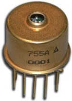 Hybrid eyesafe laser rangefinder receiver is designed for laser rangefinding & surveying equipment. Compact construction is ideal for miniature applications. Fast recovery from To overload allows ranging to close objects without compromising long range performance. The incorporation of an InGaAs APD gives very high sensitivity with time programmed gain to minimize false targets. Operation at both 1.06 µm and 1.54 µm is possible over a wide range of pulse widths.