
 sales@analogmodules.com
 1-407-339-4355


 Transimpedance Amplifier Selection Guide
AMI designs and manufactures a range of Transimpedance Amplifiers for OEM, medical and research applications primarily for use with photodetectors. AMI’s amplifiers combine low noise, high gain, large dynamic range, and small package size.
The key specifications to consider are bandwidth, AC or DC coupling, gain, noise, output swing and input capacitance.
Bandwidth

Bandwidth is a good place to start. If the amplifier cannot respond fast enough for the rise & fall of your signal you will get no output. The bandwidth specification for AMI’s transimpedance amplifiers is the 3dB point, where the output voltage has dropped by 1/√2 or 0.707 of the maximum output voltage. A great way to estimate the bandwidth of your pulse is to divide .35 by the rise time (.35/risetime). For a pulse with a 9ns rise time the bandwidth is ~39MHz. You will want to select an amplifier with a bandwidth of ≥40MHz. The calculation works in revers as well. AMI’s Model 312B-1 has a bandwidth of 200MHz or a rise time of 1.75ns (.35/200Εˆ6).
In addition to signal strength the bandwidth of the amplifier is critical when measuring the shape of signal pulse. Determine the smallest time division you need then use that value in place of the rise time. The signal pulse may have a rise time of 35ns but you want to resolve changes in 5ns steps. The bandwidth of the amplifier will need to be ≥70Mz not 40MHz.
AC or DC coupling
If the input has a constant level or very slow moving modulation you likely will need a DC couple amplifier. If the signal is a pulse AC coupling will filter out DC noise. AMI AC couples the output of our transimpedance amplifier. DC current at the input will cause the amplifier to saturate if it is too high. The input can be DC coupled but this greatly increases the noise.
 Gain, Output Swing and Saturation
Gain and output swing should be considered together. AMI’s amplifiers are designed for small signals our transimpedance amplifier have very high gain. The Model 311-1 has a gain of 1GV/A and an output swing of 7Vpk-pk or -3.5 to +3.5V into a 50Ω load. Dividing the maximum output swing by the gain calculates the maximum input current. In this case a signal greater than 3.5nA will saturate the amplifier. If the amplifier is saturated there will be no output.
Noise
AMI specifies the spectral noise at the input of the transimpedance amplifier. This allows the user to directly compare the amplifier noise to their signal. To convert spectral noise to RMS take the square root of 1.57 times the bandwidth then multiply that by the noise figure RMS=[√(1.57*bandwidth)]*spectral noise. Multiplying the input noise by the gain will tell you the noise at the output.
Input Capacitance
The fist stage of a transimpedance amplifier has a virtual ground. Capacitance across the input of these virtual ground amplifiers causes a midband frequency boost and loss of bandwidth. The frequency boost can be cancelled by adding a small capacitor across the feedback resistor. The noise also increases at high frequencies due to current flow in the input capacitance caused by the input voltage noise of the amplifier. It is important to minimize input capacitance for the best performance and AMI fits a low-capacitance input feedthrough pin as standard. Below is are graphs showing the noise and bandwidth performance versus input capacitance for several of AMI’s transimpedance amplifiers.
© Analog Modules Inc. This post may be reproduced in its entirety without editing.
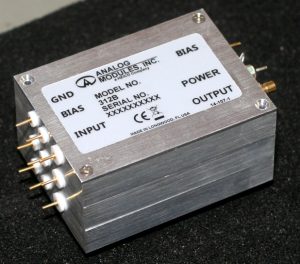
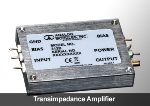
AMI’s Transimpedance Amplifiers
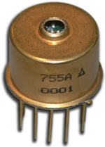 Hybrid eyesafe laser rangefinder receiver is designed for laser rangefinding & surveying equipment. Compact construction is ideal for miniature applications. Fast recovery from To overload allows ranging to close objects without compromising long range performance. The incorporation of an InGaAs APD gives very high sensitivity with time programmed gain to minimize false targets. Operation at both 1.06 µm and 1.54 µm is possible over a wide range of pulse widths.