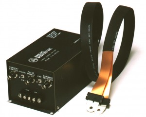
 Linear Laser Diode Driver Solution
The AMI Model 778 Laser Diode Driver was an early example of the simple linear design approach. This driver and the current version, AMI Model 779A, has been available for 25 years. In such a design, electrolytic storage capacitors are charged to a voltage greater than the diode load and current is switched into the load by linear transistors, typically FETs. The FETs are controlled from a current sense element and a feedback loop including an error amplifier that compares the demanded current with the actual current flowing. The following note describes this circuit, with RL equivalent to the diode load and showing the use of a BJT instead of a FET.
http://www.ecircuitcenter.com/Circuits/curr_src1/curr_src1.htm
A few simple statements will help in understanding this circuit:
1) To ensure that the current delivered to the diode load remains well regulated when using such a circuit, VCC must, at all times, remain at a voltage high enough to support the load and to offset other losses in the system.
2) In practice, VCC is supplied by a storage capacitor having an equivalent series resistance (ESR).
3) VCC will decrease during the output current pulse as energy is transferred from the capacitor to the diode load. This is termed droop.
4) Any voltage at VCC that is greater than that required to support the load and offset fixed losses is dissipated as power in the transistor regulator.
For optimum efficiency, droop should be minimized and VCC should be set to an initial voltage that is just high enough to offset the droop plus the voltage dropped across the various fixed losses.
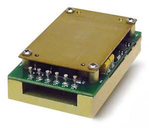 Ideally, the voltage droop would be 0V, but this would require infinite capacitance. In practice, system size constraints limit the size of the storage capacitor such that droop over the duration of the output current pulse is some fraction of the load voltage. It must be stated, however, that as the droop is allowed to increase by reducing the capacitance, the overall system efficiency will decrease. The fixed losses include the voltage dropped across the storage capacitor’s ESR, the voltage dropped across the transistor switch (Q1), the voltage dropped across the diode load (RL), and the voltage dropped across the sense resistor (RSENSE). For a single invariant operating condition, the design of such a unit is relatively straightforward.
As a real world example, consider a design to deliver 200A, 400us pulses to an 18V diode load. i = C* dv/dt, so the required capacitance for 4V of droop is (200A)(400us)/4V = 20mF. This would typically be configured as 5ea 3900uF capacitors connected in parallel, each of size 18mm diameter by 40mm height. Let’s further state that the ESR of a typical single electrolytic capacitor is 0.015 ohms (at room temp), the value of the sense resistor is 0.005 ohms, and the minimum drop across a good transistor switch at 200A is 0.3V. Best case (minimum) losses would then be, (200A)(.015Ohms)/5ea capacitors = 0.6V for ESR, (200A)(0.005Ohm) = 1V for the sense resistor, 0.3V for the transistor minimum drop, and 4V for droop. The initial capacitor voltage can then be established as; 18V (for the nominal diode load) + 4V (droop) + 0.6V (ESR) + 0.3V (transistor drop) + 1.0V (sense resistor) = 23.9V. Thus, for this design the capacitor must be initially charged to 23.9V to drive an 18V diode and the best driver efficiency that can be expected is (18V/23.9V)(100), about 75%.
As stated above, the design analysis is fairly straightforward when designing for a single invariant operating point at room temperature. The analysis is much more complicated, and disheartening, when considering the effects of temperature (-40°C to +85°C), and aging. Typical electrolytic capacitors can lose 20% of their capacitance due to temperature and another 20% due to age. The ESR of electrolytic capacitors can increase by a factor 3X over temperature and another factor of 3X due to aging. Additionally, the diode load voltage can increase up to 20% with age and 2.3mV/°C per diode with decreasing temperature. The effects of these capacitor and diode load variations are shown in the table below. The same driver design that initially yielded an efficiency of 75.3% at room temperature yields an efficiency of only 50.2% when considering all these effects.
| Typical at 20C | Spec. over T | Worst case over life | |
| Capacitance change | 0 | -20% | -36% at low temp |
| Voltage discharge drop | 4 | 5 | 6.25 |
| ESR drop | 0.6 | 1.8 | 5.4 |
| Transistor drop | 0.3 | 0.4 | 0.4 |
| Sense element drop* | 1 | 1 | 1 |
| Load variation | 0 | 3.6 | 4.8 |
| Cumulative drop, V | 5.9 | 11.8 | 17.85 |
| Peak transistor power | 860 watts | 1800 watts | 2,290 watts |
| Total C voltage with load | 23.9 | 29.8 | 35.85 |
| Driver only efficiency | 75.3% | 60.4% | 50.2% |
* Could be reduced with more complex means.
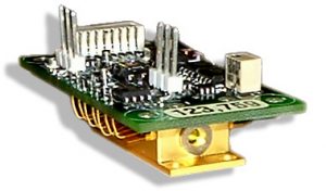 Since a unit developed for military applications must meet required operating conditions across all specified temperatures and for a given lifetime, a linear laser diode driver design must allow for expected capacitor and load variations and a fixed initial capacitor voltage must be set to a much higher voltage than is required for a brand new unit operating at room temperature. This extra voltage will be dissipated as power in the transistor switch leading to decreased efficiency and decreased reliability due to increased stresses. In the example above, the initial capacitor must be charged to about 36V to accommodate expected variations, but when operating under nominal conditions, the transistor must survive up to 16V{(36V – (18V for the load) – (0.6V esr drop) – (0.3V minimum transistor drop) – (1V for the sense resistor)} at 200 amps for 400us. This requires the use of multiple transistors to avoid exceeding the power rating and the safe operating area of any one device. In this example, the peak dissipation can be over 2KW . See the table above.
To summarize, a standard linear laser diode design is inappropriate for use in a military system, especially if commercial aluminum electrolytic capacitors are used for the storage capacitor. Normal expected variations in the capacitors and diode load due to aging and temperature require that such a design operate under conditions that are far from optimum for efficiency and reliability. The poor efficiency shortens battery life, and the high instantaneous power losses in the transistor switch require that several transistors be used to improve reliability. Linear current sources are not load fault tolerant without special circuits as a lower load voltage or short causes excessive power transistor dissipation.
MIL-HDBK-217F shows that electrolytic capacitors are 10X times less reliable than tantalum capacitors. Commercial electrolytics are not hermetically sealed and will outgas and dry out when stored at high temperatures leading to shorter usable lifetimes. There are sealed long-life capacitors available, from Evans Capacitor for example, but these are much more expensive than commercial electrolytics due to the materials used. Using this type of sealed capacitor would reduce some of the problems discussed above by limiting variations due to aging in capacitance value and ESR. This would allow the initial capacitor voltage to be set to a lower level leading to an improvement in overall efficiency of about 10% in the example cited above at the extreme case of minimum temperature and end of life.
AMI has addressed the design limitations of linear laser diode drivers in multiple ways. First, we have been manufacturing simple linear diode drivers for over 20 years and still do so for customers that desire the least expensive solution for use in a benign environment or with a short life. Second, AMI’s Model 771 driver, developed in 1986, allowed the storage capacitor voltage to be adjusted to match the instantaneous operating conditions. Third, more elaborate modules with multiple sensory inputs and intelligent automatic voltage adjustment followed. Such an improved performance intelligent linear solution is described below.
Intelligent Linear Solution
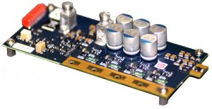 As has been shown above, a simple linear laser diode driver design must operate at a voltage that is higher than necessary in anticipation of expected changes in the storage capacitor. AMI has a patent pending which allows a safer and more reliable mode of linear operation. The intelligent linear design uses digital signal processing with various sense inputs to dynamically adjust the power supply voltage (storage capacitor voltage) to the lowest possible value and to control all aspects of the driver including emitter and power transistor protection. This concept reduces the dissipation and stress on the power transistor(s), yet ensures that there is just enough charge on the storage capacitor to meet the pumping requirements. It should be noted that this approach reduces the excess voltage stored on the storage capacitor that would otherwise be needed to accommodate potential variations in the storage capacitor and load.Any linear design, intelligent or not, must deal with the decrease in capacitor voltage due to the transfer of energy from the capacitor to the load during the output current pulse (droop). Again, increasing the total storage capacitance can reduce this droop and lessen the stresses on the power transistor, but it does so at the expense of increased size, weight, and cost.
The advantages of a linear laser diode driver are lower cost (especially if commercial electrolytic capacitors can be used), simplicity, and low EMI. Disadvantages are poor efficiency (especially if all the tolerances are considered with a fixed available power supply) and stress in the power devices leading to potentially fatal laser diode damage from the large stored energy in the event of a short. Using many large capacitors and multiple power transistors can mitigate these problems, but this increases unit size and cost. In low-current, low-noise, or high-speed applications the linear approach is frequently justified. However, just as switching power supplies have supplanted linear regulators in most applications due to their higher efficiencies and more compact designs, switching diode drivers are a better approach for high current and laser pumping applications.
In recent years, AMI has pioneered a switching type of laser diode driver that is much less susceptible to capacitor types and variation, and is much more tolerant to a wide range of storage capacitor and diode load voltages.
© Analog Modules Inc., 2016. This post may be reproduced in its entirety without editing.

 sales@analogmodules.com
 1-407-339-4355
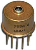 Hybrid eyesafe laser rangefinder receiver is designed for laser rangefinding & surveying equipment. Compact construction is ideal for miniature applications. Fast recovery from T0 overload allows ranging to close objects without compromising long range performance. The incorporation of an InGaAs APD gives very high sensitivity with time programmed gain to minimize false targets. Operation at both 1.06 µm and 1.54 µm is possible over a wide range of pulse widths.
