MODEL 7511A HIGH SENSITIVITY APD OPTICAL RECEIVER
APPLICATION NOTE
INTRODUCTION
The Model 7511A is a high gain, low noise optical receiver employing an avalanche photodiode (APD) with a nominal bandwidth of 35 MHz and high dynamic range capable of driving a 50 Ω load with fast saturation recovery. The output is AC coupled with a nominal low frequency cutoff of approximately 750 kHz when terminated into 50 Ω. This note discusses the performance, considerations, function and physical constraints of each pin.
PIN 1 OUTPUT
AC coupled output pulse swings negative in proportion to the input power of the optical pulse at a typical gain of 600 kV/W. Saturation occurs at a negative voltage swing of about -2 V. The signal swing deviates with temperature due to changes in APD’s dark current. If the output is connected to a transmission line, proper termination is a must since severe reflections may damage the pre-amp.
PIN 3 −5 V POWER SUPPLY
A low noise supply must be used. The maximum current draw is 16 mA with a high impedance load, or minimal signal power into the load. Bypass capacitors must be placed as close as possible to the pin. Additional filtering is recommended.
PIN 4 BIAS VOLTAGE
Apply a room temperature bias voltage in the range of 30 to 60 V to the APD at this pin as defined by the test data provided with each unit. Typical current drawn at this pin is less than 100 nA at room temperature but may exceed 4 µA at the higher end of the operating temperature extreme. Optimum bias voltage occurs at approximately 2 V below avalanche break down. A control circuitry is required to maintain signal to noise ratio by compensating the bias voltage with a temperature coefficient of 0.11 V/˚C (typical). Monitor detector’s temperature via a low current biased diode at pins 8(Anode) and 9(Cathode).
PIN 2,5, 11 NO CONNECT
These pins must be left open circuit.
PIN 6,7, 10 GROUND
These pins must be connected to the PCB ground plane on which the receiver is mounted. It is connected internally to the case.
PINS 8 and 9 TEMPERATURE SENSOR
The sensor’s main purpose is to enable the user to compensate the voltage bias of the APD for temperature. It takes advantage of the fact that when forward biased with a low constant current, the voltage across a diode’s anode (pin 8) varies by about -2.5 mV per degree C when the cathode (pin 9) is grounded. The diode must be biased with very low current (micro amps) to prevent self-heating. These nodes must be carefully filtered to prevent noise injection and loading.
PIN 12 +5V POWER SUPPLY
A low noise supply must be used for a maximum peak current draw of 26 mA. Bypass capacitors must be placed as close as possible to the pin. Additional filtering is recommended.
OPTICAL WINDOW
The optical window provides no shielding for the sensitive front end of the Model 7511A Receiver. All wiring must be routed behind the window face of the case, or oscillation can result. Additionally, system noise sources such as digital switching circuits, Pockels cell drivers, and switching power supplies should be shielded or arranged so that radiated electrical noise does not enter the receiver through the optical window. It is recommended that all switching power supplies be inhibited during the period of use and circuits supplied from reservoir capacitors. The receiver package must be isolated from chassis to prevent capacitively coupled noise injection.
DETECTOR ALIGNMENT
The hybrid must be mounted to allow movement of ± 0.025″ in any direction for optical alignment of the photodiode. If the optical system has adequate flexibility of alignment, adjustment of the receiver position may not be necessary. The focal plane is 0.14” ± 0.010” from the can base.
OVERLOAD CONDITIONS
The maximum optical signal applied to the photodiode surface must not exceed 10 mJ/cm2 or the receiver may be damaged.
GENERAL HINTS
1. Care should be taken to avoid retro reflections from a laser which could result in detector damage. The optics design should ideally spread the light spot over approximately 80% of the detector active area,
2. A low noise detector biasing power supply is available from AMI (Model 523-1-A).
3. The cases are hermetically sealed in production units and are not repairable.

Figure 1: Model 7511A-1-04 Dimensions and Package Detail
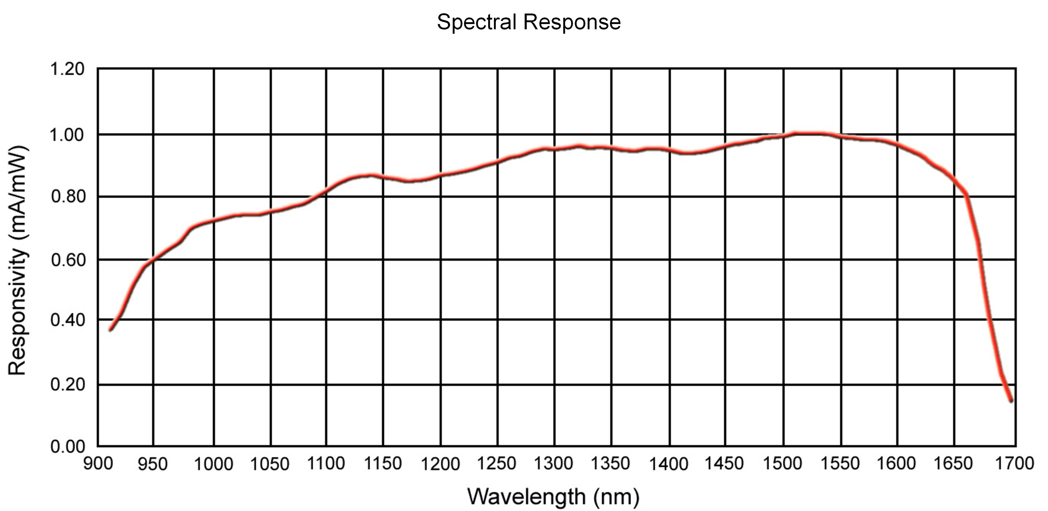
Figure 2: Spectral Response Curve
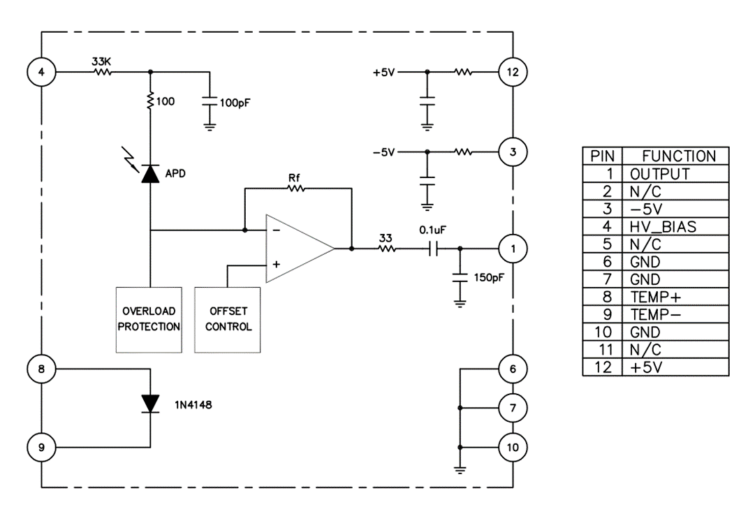
Figure 3: Simplified Block Diagram
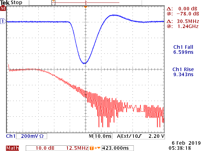
Figure 4: Typical Output Response to a 1 nS Optical Input Pulse
Ch 1 is 200 mv/div and 10 ns/div
Ch 2 is 5 db/div and 10 Mhz/div
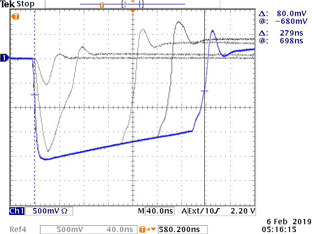
Figure 5: Saturation Recovery from a 10 mW Optical Input
Linear Dynamic Range is >20 db
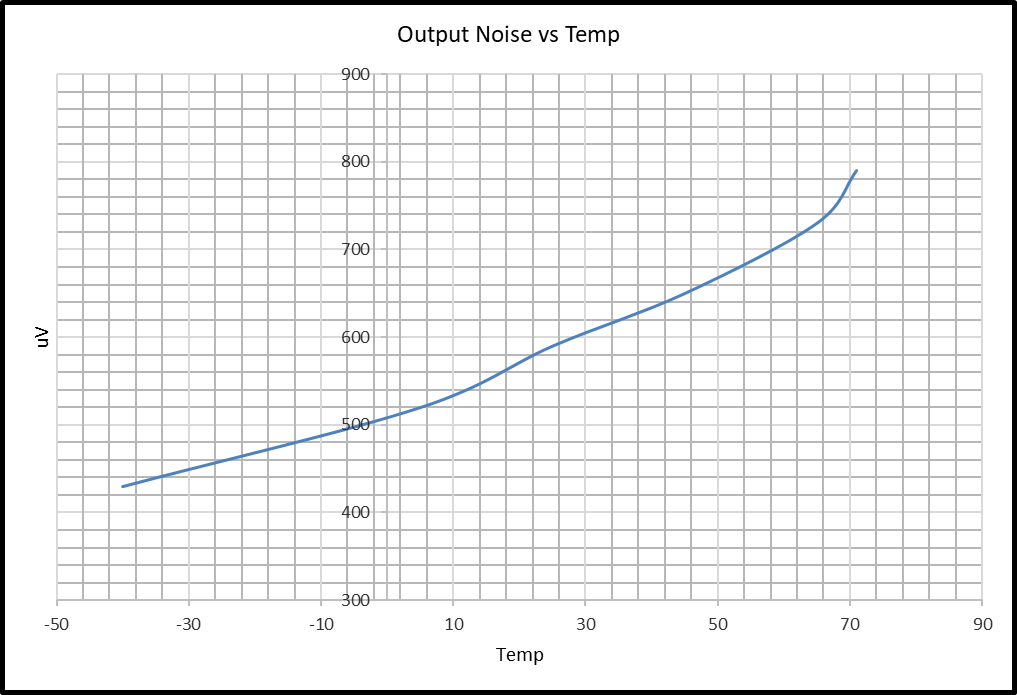
Figure 6: Typical Output Noise (µV) as a Function of Temperature (ºC)

 sales@analogmodules.com
 1-407-339-4355


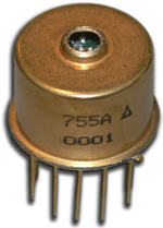 Hybrid eyesafe laser rangefinder receiver is designed for laser rangefinding & surveying equipment. Compact construction is ideal for miniature applications. Fast recovery from To overload allows ranging to close objects without compromising long range performance. The incorporation of an InGaAs APD gives very high sensitivity with time programmed gain to minimize false targets. Operation at both 1.06 µm and 1.54 µm is possible over a wide range of pulse widths.
